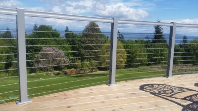
Building jurisdictions have become fairly strict and specific regarding cable railings. Technically, regardless of the span between your posts and the spacing between your cables, it is still going to be possible with enough force to spread the cables to 4″ and beyond. The issue then becomes how hard you have to push on a 4″ sphere to get it to pass through the cables. I believe most building departments require that the cables withstand 20 lbs of force.
For you and me, that means if we stick to a few guidelines our railings will meet code and pass inspection. I recommend a post span of about 4′ to a maximum of 4′ 6″. For wood frame railings, which typically use 4 x 4’s for posts, this does not necessarily mean the 4 x 4’s need to be 4′ apart. The posts could be 8′ apart with a “spreader” midspan. The “spreader” could be something as simple as a cedar 2 x 2 or a piece of aluminum flatbar, an aluminum picket or metal pipe mounted to the deck and to the underside of the rail cap. If you look closely at the wood frame railings in the photo gallery you will see this in practice.
The industry standard for cable spacing is 3″. For a 36″ railing this means that it usually takes 10 strands of cable to get to that spacing. The X factor in any cable railing is how taut the cables are. We have never used any fancy measuring tools to test the tautness of the cables. We generally tighten the cables to the point that they play a low bass note when strummed. This is quite tight and will put a noticeable strain on any rail system. To withstand that strain, it is important that especially the terminal posts are well connected to the deck framing with carriage bolts or lags, not just screws or nails. Simply nailing a 2 x 6 wood cap to the top of the 4 x 4 posts is not going to cut it. The cables will constantly pull in on the end posts and the cables will go slack. We use a 1 x 4 below the rail cap and between the posts. This creates a positive brace from one end to the other to prevent the posts from collapsing in towards the center. Many aluminum frame rail systems are already engineered adequately to withstand the strain of the cables. However, there are many more aluminum systems that are not adequate to support a cable infill. The wall thickness of the posts is key, and common sense is usually enough to determine whether a aluminum post could stand up to the strain of 10 strands of cable.
Corners
The last consideration is of cable length and turning corners. The rule of thumb is no more than two 90 degree turns in a maximum length of 90′. I would recommend staying closer to 70′ – 75′. For a wood frame railing the only way I would recommend turning the corner is with 2 posts at each corner. With only a single corner post it would be necessary to drill across the post at a 45 degree angle, and especially if the post is cedar the 10 cables would split the corner off the post. With two posts at each corner and the use of “Protector Sleeves” (to prevent the cables from cutting into the wood) it is common practice to turn the corner, this is the best way to reduce costs.
Generally a 45 degree corner is considered a “half” corner so it may be possible to make 4, 45 degree turns though one should exercise caution here, any spot that the cable binds on will make it harder to get the cables adequately tight.
All of that being said I still would not base the decision to use a single post at the corners or 2 posts on saving money on the cable supplies. Assuming you are running 10 strands of wire it will save $40 to be able to turn the corner and out of that $40 you still need to buy the second post and install it so from that standpoint it may not be worth it. Typically if your posts are mounted to the outside rim of the deck you will naturally install 2 posts at the corners, if your posts are mounted to the inside of the framing you will naturally have a single post at the corners, that should be your determining factor.
If you have single corner posts that are a common termination for two runs of cable you can still keep the cables on the same plane by slightly angling the hole up from one direction and down from the other. Depending on the size of the post that angle will only be 4 – 5 degrees which the fitting can tolerate without the use of a bevel washer to accommodate the angle. The other option is to offset the cables by 3/8″ (minimum) but for most people this is not as preferable as keeping all the cables on the same plane.
Our Philosophy Is
“Keep It Simple”!
Sleek, elaborate fittings are really cool and very expensive and mostly disappear into posts anyway. We believe form follows function and simplicity and cost effectiveness are a beautiful thing and so that’s where our approach begins. If your project requires specialty fittings we can get those. If you have a fat wallet and want cool, we can do that. If you would like affordable, simple to use fittings that’s our specialty!


